-
Here are a few design considerations when choosing between
translation and interpretation:
-
Execution speed. If interpreted, a certain amount of overhead
is required at runtime to parse and identify each instruction,
resulting in a certain amount of execution overhead. If translated,
the time to parse instructions is spent during the translation
process, not at execution time. Translation often wins here.
-
Program size. A translator from a higher level language to
a lower level language often produces a larger program file
than the original version. This has implications for the amount
of IO that would be required to load the program at runtime.
Interpretation often wins here.
-
Complexity. Translators are often more complex than
interpreters, making them more difficult to write, enhance,
and debug, although the reverse is sometimes true. This
depends largely on the nature of the language being
translated or interpreted, the nature of the target
language for translators, and the nature of the
implementation language for the interpreter and translator.
If there is an easy translation from source to target
language, translation approach will be less complex. If
there is an easy implementation of source in the implementation
language, then the interpretation approach will be less complex.
-
Portability. A translator is written in a language and
targets a specific lower level
language, while an interpreter is simply written in a
language. While both approaches are portable if the
translator/interpreter are written in a portable language,
the translation approach may require extensive modification
to the translator in order to target a new lower-level language.
-
Memory. In order to execute a program using the interpretation
approach, both the interpreter and the program being interpreted
must be present at runtime. In order to execute a program using
the translation approach, only the translated program must be
present at run time. Depending on the size of the interpreter
and the relative expansion/compression during translation, one
approach may be preferable over the other from a run-time
memory resource requirements perspective.
-
Let x be the number of instructions executed during the run, not
including those required to implement the new instruction. Then
(x + x * 0.05 * 20) * 100 nsec per instruction *
1 second per 10**9 nsec = 100 seconds. Then 2x / 10**9 instructions
= 1, or x = 500,000,000 instructions.
If we use the microprogrammed approach, 95% of the instructions take
100 nsec each, while 5% take 20 * 10 nsec = 200 nsec each. So,
500,000,000 * ( 0.95 * 100 nsec + 0.05 * 200 nsec ) =
500,000,000 * ( 95 nsec + 10 nsec ) = 52.5 seconds.
-
Let y be the number of instructions executed during the run, not
including those required to implement the new instruction. Then
(y + y * 0.05 * 20) * 100 nsec per instruction *
1 second per 10**9 nsec = 50 seconds. Then y / 10**9 instructions
= 1, or y = 250,000,000 instructions.
If we use the hardware approach, then all 250,000,000 instructions
may be completed in an average of 100 nsec, or 25 seconds total.
-
105 base 7 = 54 base 10, 110110 base 2, and 36 base 16.
-
1023.0625 = 1111111111.0001 base 2, 3FF.1 base 16, 1777.04 base 8.
-
-1234 base 10 = 1111 1011 0010 1101 base 2 (16-bit one's complement).
-
-2345 base 10 = 1111 0110 1101 0111 base 2 (16-bit two's complement).
-
10000001 base 2 (8-bit one's complement) = -126 base 10.
-
10010011 base 2 (8-bit two's complement) = -109 base 10.
-
0110101 + 10001000 (8-bit two's complement addition) = 11110001 base 2
(8-bit two's complement), -15 base 10.
-
-129.0625 base 10 = C301 1000 (32-bit hexadecimal IEEE single-precision).
-
CDB0 0000 (32-bit hexadecimal IEEE single-precision) = -22528 base 10.
-
3FC0 0000 + 3FA0 0000 = 4030 0000 (32-bit hexadecimal IEEE single-precision) =
2.75 base 10.
-
BFD0 0000 * BFB0 0000 = 400F 0000 (32-bit hexadecimal IEEE single-precision =
3.875 base 10.
-
65536 4-bit words = 32768 bytes.
-
2**4 = 16.
-
960 * 8 * 32 * 512 bytes = 120 Mbytes.
-
100 + (10 msec + 80 msec) * 960 = 86.5 seconds.
-
1.4 Mbytes/second.
-
8 * 32 * 512 bytes = 128 Kbytes.
-
4.
-
0000000.
-
1001100.
-
1101101 = 0101.
-
0101100 = 0101.
-
56000 bits per second / 8 bits per byte = 7000 bytes per second.
700 Kbytes * 1024 bytes per Kbyte / 7000 bytes per second = 102.4 seconds.
-
19200 bits per second / 10 bits per byte = 1920 bytes per second.
384 Kbytes * 1024 bytes per Kbyte / 1920 bytes per second = 204.8 seconds.
-
110 bits per second / 11 bits per byte = 10 bytes per second.
2 Kbytes * 1024 bytes per Kbytes / 10 bytes per second = 204.8 seconds.
-
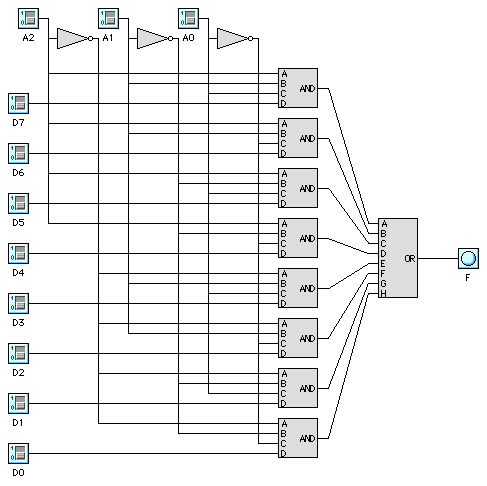
A~B~C + ~AB~C + ~A~BC + ABC; this is the parity function, i.e.,
produces 1 if A, B, C are of odd parity.
-
15 nsec.
-
19, one for each input to a NOT, NAND, or NOR gate.
-

-
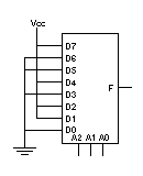
We simply connect D1, D2, D4, and D7 to Vcc, and the other Dx
inputs to Ground. F is then produces the parity of A0-A2.

-
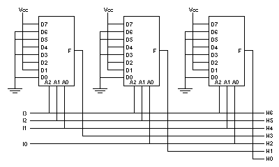
Since each parity bit (H0, H1, and H3) is derived from exactly 3 other
bits, we can connect the outputs of the three muxes to H0, H1, and H3,
respectively, and the inputs to the appropriate input lines for the
muxes, as illustrated in the following diagram:

Here, I0-I3 are the 4 input data bits, and H0-H6 are the 7 output.
It is interesting to note that this implementation requires a
minimum of 43 * 3 = 129 transistors. If we use 3 parity functions
implemented directly, only 19 * 3 = 57 transistors are required.
If we implement the circuit using discrete logic components, no
more than 52 transistors are required (we can economize on NOT gates).
Note, however, that the
3 mux approach only involves 2 gate delays, while the other two
approaches involve 3.
-
In a horizontal microarchitecture, each bit in the control
store directly controls a single control line in the data path.
In a vertical microarchitecture, a small number of bits
in the control store are decoded to control a larger number of
control lines. In general, a horizontal approach involves
a wider control store, but is capable of greater speed. The
vertical approach requires a narrow control store, but must be
decoded in order to drive the actual control lines, thus
introducing a delay in driving the control lines.
-
Nanoinstructions are used to drive a lookup table of
microinstructions in a machine where a nanostore is
used. This is appropriate where many of the microinstructions
occur several times through the micro program. In this case,
the distinct microinstructions are placed in a small control
storedex. The nanostore then contains (in order)
the index in the microcontrol store of the appropriate microinstruction.
-
At each step in the data path, different events need to occur, each
step corresponding to a clock sub-cycle. For example, in the first
subcycle, the control lines may be latched, in the second subcycle
the input register values may be latched, and in a subsequent cycle
an output register values may be latched by the scratch pad.
-
100.
-
150.
-
140.
-
Typically, all parameter values and the return address are
placed on a stack prior to the call to a subroutine. Upon
exit, the return value and parameter values are removed.
The instructions used to implement this are often PUSH,
CALL, RETURN, and POP.
-
There are many solutions. Here is one:
0001 xxxx yyyy zzzz
 :
0110 xxxx yyyy zzzz

0000 0001 xxxx yyyy
 :
0000 1100 xxxx yyyy

0000 0000 0001 xxxx
 :
0000 0000 1111 xxxx

0000 0000 0000 0000
 :
0000 0000 0000 1111
-
X A B - C D - E / + F * =
-
MOVE A,R0
SUB B,R0
MOVE C,R1
SUB D,R1
DIV E,R1
ADD R0R1
MUL F,R1
MOVE R1,X
-
7 operands * 2 bytes per operand + 8 instructions * 2 bytes per instruction =
30 bytes.
-
PUSH A
PUSH B
SUB
PUSH C
PUSH D
SUB
PUSH E
DIV
ADD
PUSH F
MUL
POP X
-
7 operands * 2 bytes per operand + 12 instructions * 1 byte per instruction =
26 bytes.
-
An interrupt is typically initiated by the I/O hardware
and causes the CPU to stop what it's doing and invoke an interrupt
service routine, and then continue. A trap is typically
initiated by the CPU in response to some condition which has occured,
numeric overflow, for example. Here also, a service routine is
typically invoked.
-
A protection fault occurs when an operation (usually read, write, or
execute) is attempted in a segment that is flagged as prohibiting the
particular operation. A segment fault occurs when the requested
segment is not present in memory. A page fault occurs when the
requested page is not in memory.
-
Assemblers are implemented as multi-pass translators to allow
forward references. For example, to allow macros to be used
before they are defined, an initial "macro defining" pass
might precede other passes. More importantly, in order to
allow a forward jump (e.g., jump to the instruction following
the end of a loop), the address associated with the label
would not be known unless a previous "label defining"
pass had been completed.
-
A module might include an identification section, an entry
points section, an external references section, a code/data section,
a relocation dictionary section, and a end-of-module section.
-
6.
-
6.
-
16.
-
15.
-
Single Instruction stream, Multiple Data stream. In this
architecture, a single control unit is broadcasting instructions
to multiple processing units which are carrying the instructions
out simultaneously, each on a separate data set. The connection machine,
ILLIAC IV, and other array and vector processors are examples of this
architecture.
-
Multiple Instruction stream, Multiple Data stream. In this architecture,
each processor is executing its own instructions against its own data.
Modern multi-processor machines are often of this type. Also,
parallel virtual machines may be said to be of this type.
-
10.


